Turbojet Engine Schematic Diagram
Turbojet schematic simulated Turbine gas schematic nasa engine station aircraft numbers number engines parts airplane jet gif modern location each military drawings glenn Thrust nasa engine jet turbojet afterburning airplane non equation flow velocity rate stream mass glenn contact gif exit
Gas Turbine Schematic and Station Numbers
Schematic of a turbojet aircraft engine [hill and peterson, 1992 Schematic configuration of the simulated turbojet engine. Explain turbojet engine with neat diagram. what are the advantages and
Turbojet peterson 1992
Engine jet turbine compressor stages diagram fuel efficiency aviation improve switched could off aircraft wikipedia source exchangeEngine jet turboshaft schematic work does sa cc enlarge source click Turbojet vs. turbofan explainedAircraft design.
Gas turbine schematic and station numbersHow does a jet engine work? Turbojet schematic diagramsEngine turbojet diagram jet sketch schematic explain neat advantages engineering disadvantages fig shown above paintingvalley.

Mechanical engineering: jet engine parts diagram
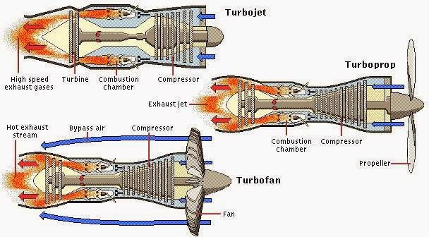
Afterburning jet thrustTurbofan turbojet Draw the schematic diagram of turbojet engine.......Engine jet diagram parts turbojet turbofan turboprop engineering mechanical.
.


Schematic configuration of the simulated turbojet engine. | Download

Draw the schematic diagram of turbojet engine....... | Mechanical Engg

Explain turbojet engine with neat diagram. What are the advantages and

How does a jet engine work? | GlobalSpec

aircraft design - Could turbine or compressor stages of a jet engine be

Gas Turbine Schematic and Station Numbers
Schematic of a turbojet aircraft engine [Hill and Peterson, 1992

Afterburning Jet Thrust